Speed and Efficiency in Next-Generation Rolling Mills
The efficiency of a modern rolling mill also depends on the quality of its mechanical components, especially transmission couplings and torque limiters to ensure the correct rolling force under all operating conditions. R+W, a company of the German Poppe & Potthoff group specialising in power transmission components for industry, offers specific solutions which guarantee safety and reliability under extreme load conditions.
In order to respond to customers’ need for quality, performance and ever-faster timescales, Italian companies involved in the rolling industry have adopted an operating philosophy inspired by Industry 4.0. Especially in difficult market situations, operators are called upon to redesign processes and methodologies in the light of technological innovation. For companies in the sector, this means adopting advanced technology machinery made using next-generation, that is, intelligently designed mechanical components. This is the case with R+W; in order to meet the needs of companies to have increasingly high performance machinery, this suplier exploits material science as much as possible, using products capable of combining lightness and performance. An example in this direction is provided by R+W’s ZAL series of line shafts made using composite material. Simple and quick to assemble, completely backlash-free, ZAL line shafts are made with fully detachable clamps and intermediate section in carbon fibre composite material, thus combining lightness and rigidity. A system entirely designed using light mechanics consumes less energy and is therefore more efficient.
An important contribution in terms of plant efficiency is also provided by the ST series torque limiters by R+W: these are modular safety couplings which can prevent machine downtime due to torque overloads and therefore guarantee continuity in production. Made of high-strength burnished steel, they are absolutely maintenance-free. They can be easily and quickly reset, allowing a prompt restart of production and avoiding costly and prolonged machine downtime.

Figure 2: Schematic representation of a rolling plant 
Figure 3: Main configurations of a rolling plant
The rolling process
The rolling process makes it possible to reduce the thickness or change the cross-section of a material by means of compression loads exerted by rollers. For large part of steel and non ferrous metals, rolling is the first process used in the conversion from raw material to semi-finished or finished product.
The metal is passed between two rollers that rotate in opposite directions, positioned at a distance which allows an opening narrower than the thickness of the incoming metal. As the rollers rotate at a peripheral speed higher than the speed of the incoming metal, the friction arising along the contact interface causes the metal to be pushed forward. The metal is thus compressed and stretched to compensate for the decrease in thickness and cross-section area. The rolling process has two fundamental variants: hot rolling and cold rolling. In hot rolling, shown schematically in Figure 1, temperature control is fundamental for the correct execution of the process, similarly to all other high temperature processes. Hot rolling processes generally end when the temperature is between 50 and 100 °C higher than the recrystallization temperature of the material being rolled. Cold rolling can be used in the production of sheets, strips, foil, bars and other profiles with high levels of surface finish and accurate dimensions.
The deformations that come into play in the cold rolling process are limited, while the loads acting on the rollers are considerable. This results in a different approach to the design of handling systems, as the drive components have to operate under severe conditions.

Figure 4: Flexible gear coupling in the R+W BZ series 
Figure 5: R+W ST series torque limiter
The main components of a rolling plant
A rolling plant, schematically shown in Figure 2, basically consists of rolling trains (with one or more cages), reheating furnaces (in the case of hot rolling) and accessory devices. The rolling cages constitute the frame in which the rolling rollers are housed; they are generally made up of sturdy uprights in cast steel and stiffened by suitably sized crossbeams. The same rollers are then equipped with bearings, suitably fitted at the ends and inserted in special seats called ‘cranksets’. Generally, a rolling roller has a central part that acts directly with the material during rolling, pins on which the bearings housed in the cranksets are fitted and arrangements for kinematic coupling with the line shafts. The main configurations of a rolling plant are given by the arrangement of the rollers in the rolling cage (Figure 3). The rolling cages are also equipped with height repositioning systems for the upper rollers and systems for checking the planarity of the laminate in order to avoid processing errors, such as laminate thickness unevenness and edge cracking.

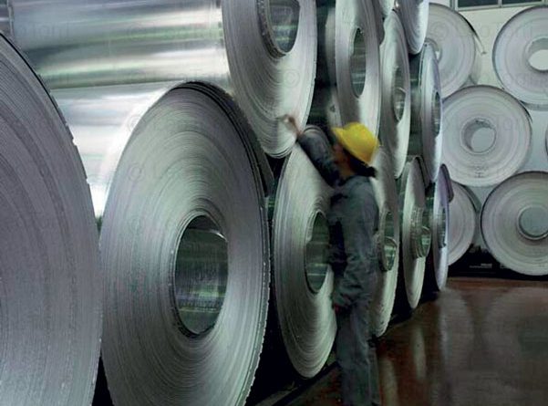
Laminazione a freddo di foglio d’alluminio 
Laminazione a freddo di foglio d’alluminio 
Laminazione a freddo di foglio d’alluminio
The transmission components in general include:
– a flywheel, which has the task of accumulating kinetic energy to compensate for the greater effort required from the electric motor in phases such as roughing, while keeping the rotation speed of the rollers constant;
– a cage-pinion gearbox, which has the task of transmitting and distributing the torque from the motor to the extensions, by splitting it; it generally consists of a series of helical toothed gears and is sometimes equipped with bevel gears with Gleason toothing;
– line shafts;
– flexible gear couplings and torque limiters
R+W’s transmission components are compact, precise and offer a high level of flexibility. An example of a flexible gear coupling is shown in Figure 4. Figure 5 shows a torque limiter of the type used in combination with flexible gear couplings.
The role of the component supplier
A complex activity such as the design of aluminium rolling equipment can find valuable support in component suppliers. This is the case of R+W, a leading company in the production of couplings and line shafts, able to make its experience available to the designer. In the sector of aluminium rolling plants, R+W provides specific solutions for torque transmission requirements. In addition to the already mentioned torque limiters in the ST series and carbon fibre line shafts in the ZAL series, R+W also offers BZ series flexible gar couplings which are used in combination with ST safety couplings.
Strong, sturdy and compact, R+W flexible gear couplings have a high torque density and are widely used in heavy industry applications – such as motion transmission in rolling mills. The flexible gear couplings transmit torque from 1,900 to 2,080,000 Nm with high torsional rigidity and low backlash. To ensure an excellent performance, R+W produces both coupling hubs and flange sleeves with precise toothed profiles made from high-strength steel. The flexible gear couplings also allow high compensation of misalignments with low return forces; safe torque transmission is achieved by means of fine threaded precision screws. The use of R+W transmission couplings allows the realization of drives with the ability to control the planarity of the rolled product, avoiding common processing errors such as thickness unevenness and edge cracks. The onset of these errors is linked to the nature of the loads acting on the upper roller of the rolling cage, which are dealt with by the characteristics of flexibility, high torsional rigidity and compensation of misalignments typical of R+W couplings.