
The “digital twin” at the service of electrical designers
The advent of Industry 4.0 and the acceleration of digitization processes in all company departments have developed the need to have the “digital twin” in the technical office. While three-dimensional design has been an established topic for mechanical designers for more than 20 years, the situation is a little different for electrical designers.
by Gruppo Meccatronica di ANIE Automazione
The design of the electrical diagram is only and exclusively two-dimensional and it could not be otherwise, however, there are three specific areas of electrical design in which, thanks to the latest technologies, this aspect can be questioned such as in the construction of the switchboards in 3D, in the on-board wiring and cables in the field. These are three completely different dynamics but with one aspect in common: the two-dimensional electrical diagram, which is the starting point from which it is possible to extract data and models on which to make calculations and simulations. Let’s see what they are in detail.
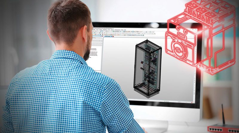
3D control panel building: a growing need
Designing a 3D switchboard is becoming an important requirement because it has been proven that the time spent on the design pays off in the engineering, building and maintenance phases. It is necessary to define exactly the spaces between a component and another, verify the interferences and make a thermal analysis to choose the best cooling system. But that’s not all, thanks to the 3D panel it is possible to have automatically the drilling templates, the filling coefficient of a duct, the automatic unraveling of the wires and the complete mapping of the connections. With the use of a tablet the operator can follow, in a precise and detailed way, the wiring indications and the path of the cables. Thanks to the “digital twin” the operator knows which path to follow for each wire, to which terminal to connect it and in which channel it should pass. This process ensures the realization of one or more electrical panels in accordance with the original project, free of errors and fully responsive to customer requirements. Subsequently, it is possible to “connect” the project with machining centers, such as milling machines and cable processing machines, to create a dedicated “Cad-CAM” environment. The software that generates the 3D project, sends an input to the machining center that drills the plates and prepares the slots of the cabinets and boxes, to the machine dedicated to the assembly and marking of the terminals, and finally to the one that cuts the single wire to size, heads it and labels it. Service operations are also facilitated by the creation of a digital prototype of the panel in 3D. The documentation of the 2D and 3D electrical design of the machine can reside in the cloud. The operator equipped with a tablet accesses the plant where a fault has been reported, for example of a motor, frames the QR Code with the camera, thanks to augmented reality the cabinet is displayed in 3D that highlights which terminal is connected and which wiring diagram it refers to. All this without having to use paper manuals. The use of these new technologies challenges the traditional way of working of OEMs, where the mechanical designer does not deal with electrical design. In a modern view, this is not the correct approach as machine design and panel engineering must be generated from a single source capable of producing the design based on a 3D model. Instead, the new approach allows the entire ecosystem (End User/OEM/ Panel Builder) to take full advantage of the benefits of process digitization.

Digital prototypes for machine on-board cables
As far as on-board cables are concerned, the situation is a little different. The needs of OEMs are twofold. Manufacturers of standard machines need to know, before the machine is physically built, all the information needed to wire it: number and type of wires, connectors, cable bundles, etc., in order to order the necessary material in advance and have it available when the machine is assembled in the workshop. On the other hand, manufacturers of special machines must anticipate as much as possible any problems they might have during construction: impossible routes, mechanical interference, magnetic interference, vibrations, etc. In both cases, technology can support them. Mechanical designers finish the digital prototype of the machine or plant with 3D mechanical CAD and pass it to the electrical designers, who import the model through dedicated software and in an easy and intuitive way deal with the arrangement of cables and wires inside the machine. They check passages, diameters and hole sizes, and if they find a problem, they report it to mechanical design, which will make changes to the design before the machine is built. When undocumented changes are made it creates criticality within the commissioning and maintenance process at the customer’s site.
From a CAD perspective, the result is a hybrid “mechanical and electrical” model that offers the ability to easily extract all the cable lists, lengths and nail tables needed to manage cable bundles with connectors.
Digitization is the best choice for cables laying in the field
Finally, cables in the field. Think of a large plant, a steel mill or a refinery. Imagine the kilometers of cable that must be purchased, routed and prepared. If an error were to occur during the purchasing phase, for example by ordering 10 kilometers of cable with the wrong diameter or an error in laying them out, there would be an increase in costs and production time. Digitization is the optimal solution to avoid this kind of situation. The lay-out of the steel plant is imported into the electrical environment and through special tools the laying of the cables in the available spaces, in the different floors of the offices, in the electrical panels, in the junction boxes, etc. is done. As a final result we will have a digital model of all electrical systems, complete with list of materials and supply lists. Three concrete examples were cited that are experienced every day when talking to customers, and real solutions that have been established for years. The technologies available today and the benefits offered make this ecosystem easily implementable, it is necessary to apply some structural and cultural improvements to achieve a future-proof technological development.