
Electric and Hybrid Engines: the Evolution of Testing Systems
Electric cars are generating the most interest in the industry and the supply chain is evolving to keep abreast: starting with test benches for electric and hybrid engines, interconnected with control systems and road tests, which have advanced data collection capabilities. R+W is able to provide this sector with a complete range of couplings for all precise and balanced transmission requirements.
Electric cars are gaining significant market share, prompting the automotive industry to innovate in order to keep up with market developments. This also applies to the testing segment, which is becoming increasingly hi-tech: the test benches used to test and certify green engines are undergoing a real revolution. Products are becoming increasingly sophisticated in order to ensure high quality standards for car manufacturers: carrying out the appropriate tests to verify vehicle performance in terms of emissions, fuel consumption, robust diagnostics and speed is crucial to differentiating one product on the market from another and beating the competition.

In a highly competitive industry innovation is crucial
High-performance components (torque transducers, inverter motors and couplings) are used to build the test benches. Operating at high speeds, the benches require fast, light, precise and balanced couplings. These components are complemented by extensive electronic instrumentation and sophisticated management software to ensure the high performance required by the competitive and ever-changing automotive industry, where innovation is crucial. Test benches for this sector must take into account advances in both hybrid and electric powertrain systems.
All parameter tests must be reproducible and targeted
Test benches are an essential tool in powertrain engineering. Their use generally precedes the road-testing of a new vehicle across its entire engine range. It is therefore essential that specific characteristics can be tested in a reproducible and targeted manner under predefined boundary conditions.
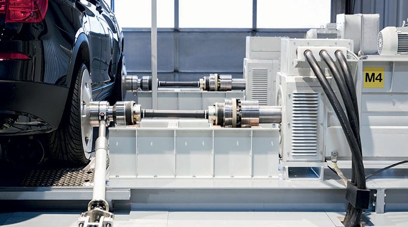
Modern systems of this type also make it possible to collect the results of road tests in a procedure called road-to-rig (R2R). Figure 1 shows the typical setup of a new car test on a test bench implementing the R2R procedure. The solutions chosen for the kinematic couplings, similar to those shown in the figure, will have to cope with the inertia compensation requirements. The test bench will thus be prepared to conduct tests for all types of car, from small cars to SUVs. The kinematic chains must therefore have the characteristics of low rotational inertia, lightness and compensation of misalignments. Taking these requirements into account, their construction will also be fundamental for the construction of a test bench capable not only of conducting tests on the types of vehicle indicated above, but also of maintaining its configuration practically unchanged. Such a system has the considerable advantage of being able to be used at any stage in the development of a new vehicle and its complete propulsion system, based on both hybrid and electric engines. Clearly, this has the considerable advantage of reducing the number of expensive vehicle prototypes to be launched on the market for road testing.

The evolution of test benches for electric and hybrid powertrains
Over the last decade, test benches have evolved steadily. Starting from the observation of the operating conditions of test benches for propulsion systems based on conventional engines, research activities have aimed at establishing new test strategies for hybrid and electric engines.
Since 2011, the Institut für Verbrennungsmotoren und Kraftfahrwesen Stuttgart (IVK) at the University of Stuttgart has been systematically analysing all test requirements and operational parameters for the design and subsequent construction of test stands for hybrid and electric engines.
In the case of hybrid and electric vehicles, there is a need for an on-board power supply network, which is essential for powering one or more electric motors. For this reason, it is logical to extend the functionality of the test bench for an innovative propulsion system with a test section for the on-board power supply, in order to evaluate the interactions between the mechanical and electrical systems. This solution proves to be non-limiting in terms of coupling energy, as shown briefly in the following example.

The application example of a test bench for a hybrid vehicle
Consider the measured current of the traction battery in a parallel hybrid vehicle. The rotational irregularities of the internal combustion engine, as well as the mechanical rotational frequencies, can easily be detected in the frequency spectrum measured by the instrumentation. The combination of the rotational irregularities of the internal combustion engine and the mechanical rotational frequency constitute a de facto forcer and load for the electrical system. Figure 2 shows a schematic representation of the test bench, in which an all-wheel drive system, in parallel with a hybrid propulsion system, is tested. As far as the drives are concerned, there are four highly dynamic electric load machines; the rotational moment of inertia of each of them is equal to that of a wheel of a production vehicle. The position on the bench of these loading machines can be adjusted along the three directions in space, so that the testing of propulsion systems of different sizes can be facilitated. These machines are then connected in place of the wheels, at the flanges of the hubs of the propulsion system to be tested, by means of couplings that realise the kinematic chains whose requirements have been described above.
The test is carried out by applying one of the following methods:
- The engine of the powertrain under test is used;
- another high-dynamic electrical loading machine is used, capable of replicating the rotational irregularities produced by internal combustion engines at various frequencies, up to a maximum of 500 Hz.
By applying the second method of testing, a moment of inertia within the same range of values as that of a car internal combustion engine can be obtained.
Regarding the power supply, a high-dynamic, 2-quadrant DC source is used (that is, a DC source whose circuit makes available an armature voltage which is always) positive, while the current will be positive or negative, so that the quadrants of the i,v plane involved are 2). Using this device it is possible to simulate the presence of batteries which are not really installed.
If an energy storage device is present, the voltage source can also act as an additional energy consumer, simulating the action of the test and recharge systems of the standard battery.
A control panel with integrated current and voltage measuring instruments and multiple contactors forms the interface for conducting the powertrain test.
The latter provides additional protection functions in the event of an error and can be used to selectively simulate cable breaks and short circuits in the windings.
For the 14V electrical system, which is used in both conventional and alternative propulsion systems, an additional regulated source is made available. By using this source, the increasing demand for electrical energy in the system due to the electrification of auxiliary units is taken into account, as well as the impact associated with fuel consumption.
An integral part of this automation system, consisting of several real-time synchronous computers, is a simulation system on which the rapid control processes are implemented.
The ability to adapt to existing models and to integrate new ones developed by means of numerical calculation software and modelling, simulation and analysis of dynamic systems is an additional feature of test benches for both hybrid and electric powertrains.
The combination of hardware and software equipment, particularly interfaces, facilitates the synergy of simulation, test bench and road test activities.
Careful dimensioning of the kinematic couplings provides the additional advantage of making the test bench solution scalable.
The test bench configuration shown here allows for two separate automation systems, so that the scheme based on an all-wheel drive transmission, considered in the initial example, can be split into two independent single-axle test bench schemes.
Figure 3 shows the main different test bench configurations achievable for conventional, hybrid and electric powertrains.
The flexibility of the test bench allows R&D activities to be optimised by adjusting the operating parameters of individual components or even removing them in order to allow testing of high performance electric powertrains and to highlight, in the case of hybrid powertrains, the performance improvements and cost increases associated with the introduction of the relevant electric systems.
Such strategies also require the use of control units capable of providing additional emission pattern prediction functionality, so that the design of kinematic couplings, respecting the above requirements, plays a fundamental role in the achievement of useful test results.

The role of the component supplier
A task as complex as designing test benches for hybrid and electric powertrains can be supported by component suppliers. This is the case with R+W, which provides the industry with a comprehensive range of solutions for all precise and balanced drive train requirements, such as the BK series precision metal bellows couplings and LP series disc pack drive couplings. BK series precision metal bellows couplings and LP series disc pack transmission couplings are very strong and have the ability to work at very high speeds. They are also precise, resistant to stress, wear and temperature fluctuations – qualities that make them suitable for particularly high dynamics. Versatile and backlash-free, these couplings are also highly appreciated for their low moment of inertia, their total lack of maintenance, their virtually unlimited service life and, above all, their total reliability. The combination of these features makes them well suited to meet the ever-increasing efficiency demanded by the growing competitiveness of the automotive industry and the continuous increase in speed and performance requirements. LP disc pack couplings are used in steel plants, conveyor belts, pumps, test benches and many other applications. They are strong, compact and provide high torsional rigidity. The optimised hub profile, which has cavities in the area around the fixing screws, reduces material usage and weight, resulting in a lower mass moment of inertia. Thanks to the use of highly resistant material, all series have a high power density.